In the first two posts for switching wie first checked how to process a put request in the Node-RED plugin of the SignalK server and then how to generate it from the Arduino. In this part we approach the other side of the chain using a shield with smart FET’s to switch and observe a load.
Hardware and Software in use
- PC with Debian GNU Linux 10.0
- Raspberry PI 3 with Raspbian Buster Lite (02.12.2020) (Configuration is described here)
- Arduino IDE 1.8.13
- Arduino MEGA 2560
- Wiznet W5100 Ethernet-Shield
- Infineo High-Side-Switch Shield BTS7002-1EPP
- The ArduinoHttpClient Library Version 0.4.0
- The ArduinoJson Library Version 6.17.2
- The High-Side-Switch Library in Version 0.1.0
Why using a smart FET?
Because the outputs of a microcontroller like the Arduino can not switch high currents, they need further components to switch high loads. Today, for such applications field effect transistors (FET’s) are established for such applications because they have a very high input impedance. They can switch high currents without being a high load for the microcontrollers output itself [1]. A FET alone would already be sufficient for that task alone, but here we decided to use the Infineon PROFETTM, which is a smart FET. Additionally to switching the load, it is able to measure current and has some protection and diagnostics functions e.g. for over temperature, short against ground, short agains supply voltage and more [2]. What comes handy for us is that there is a line of Arduino compatible “High Side Switch” (HSS)-shields available using the PROFETTM‘s (we’re using the BTS7002-1EPP here) so that we can easily build up a prototype.
Details about the sketch
You can find the sketch in our github at https://github.com/Vehicle-Hacks/Arduino-SignalK/releases/tag/v0.4.0 or you download it using git:
git clone -b v0.4.0 https://github.com/Vehicle-Hacks/Arduino-SignalK.gitThe sketch presented here is an extension of the sketch shown in the last post. Theoretically it is possible to use one arduino to read in the push buttons and to switch the loads. The problem is, that currently it’s not possible to send a put request by UDP or TCP, that’s why we had to use a websocket connection in the last post. Using the websocket connection the full packet is built together in the (little) SRAM of the Arduino, which is not enough for building the complete message containing the load status. So, in this sketch we combine websocket and UDP communication, which is not nice but working for now. In total there are only few lines added and most are already known from the post “Arduino Uno as SignalK Source”. So here is only a little overview about the differences without repeating to many details of the code.
In the top part of the sketch the includes for the HSS shield and the global variables for HSS shield and UDP communication are added. To the JSON strings stored in flash memory we added some for the communication of load/smart FET status. In the lower part of the setup() function the (already known) initialization of UDP is added and the HSS shield is initialized.
In the loop() function the modifications start in the section, which reads in the push button and communicates status changes to the SignalK server. For this post, switchting the smart FET is hard coded here, so the sketch is not waiting for the response of the SignalK server but switching the FET state synchronously to the switchState of the Arduino. For switching the FET’s, the HSS shield library provides a function for switching on or off the smart FET’s, which is added to the corresponding sections:
      if (switchOutput == false) {
        switchStateChanged(1);
        targetState = 1;
        ledBlinking = true;
        switchOutput = true;
        HSS.switchHxOn(1);
      } else {
        switchStateChanged(0);
        targetState = 0;
        ledBlinking = true;
        switchOutput = false;
        HSS.switchHxOff(1);
      }
There is one thing to take care of: The four switches are not numbered from 0-3 as you would expect in C/C++ but from 1-4. In the lower part of the loop() function the supply voltage and the current of the first smart FET is read out using HSS.readVSS(1) and HSS.readIsx(1) and sent to the SignalK server using the principle shown in “Arduino Uno as SignalK Source”. Before executing the sketch let’s have a look at the hardware setup for the test.
Hardware Setup for Testing
We’re using two shields, additionally a LED and a push button are connected. To check if both shields are compatible with each other – there are no conflicts between pins – and to know where to connect LED and push button we first need to have an overview how both shields are using the pins. The pin layout for the HSS shield is documented in the user manual [3]. The pin layout for the ethernet shield can be found in the schematic [4]. The table below contains all relevant pins. The pins where a multiple use is not critical (e.g. +5V. +3.3V, GND) are not listed.
The HSS shield is using four of the Arduinos digital ports as outputs to switch the PROFETTM‘s (in the user manual and in the table they are called IN1-IN4 as seen from the PROFETTM‘s side). Four further digital ports are used to switch the LED’s on the HSS shield. One analog in is used to measure the supply voltage and to further analog in’s to read the current through FET 1/2 and FET3/4. One analog in is planned for reading an analog button but the components are not on the shield. Two further digtal ports are used for diagnosis enable, one for “Open Load in OFF” detection and another one for an optional digital push button. In total, four of six analog ports and 12 of 16 digital ports are in use by the HSS shield.
The large number of pins in use leads to some used by both the HSS and the Ethernet shield. Many of the double pins are conflicting with the six tinker kit connectors on the Ethernet shield which aren’t a problem as long as nothing is connected to them. The Ethernet shield is using the ICSP header for the SPI bus which is not used by the HSS shield so there are no conflicts with the bus. Pin D13 is used for a LED on both shields (as on the Arduino itself) which also is not problematic.
At the end, there are two potentially conflicting pins: Additionally to the Wiznet W5500 there is a micro SD slot on the Ethernet shield. Both are using the same SPI bus and each is using one pin of the Arduino to chose the W5500 or the micro SD for communication. For the micro SD the pin D4 is used and for the W500 the pin D10. Theoretically we have to ensure that D4 stays on high and D10 on low. During practial tests with both the HSS and Ethernet shield there haven’t been problems when switching D4 and D10 also with an SD card in place.
| Arduino pin | shield/component | function |
| A0 | High Side Switch | push button – optional |
| A1 | High Side Switch | BAT+ by voltage divider |
| A2 | High Side Switch / Ethernet shield | HSS: IS1 + IS2, Eth: TinkerKit IN2 |
| A3 | High Side Switch / Ethernet shield | HSS: IS3 + IS4, Eth: TinkerKit IN3 |
| D2 | High Side Switch | push button – optional |
| D3 | High Side Switch | IN3 (FET 4) |
| D4 | High Side Switch / Ethernet shield | HSS: LED1, Eth: slave select micro SD |
| D5 | High Side Switch / Ethernet shield | HSS: LED2, Eth: TinkerKit OUT5 |
| D6 | High Side Switch / Ethernet shield | HSS: DEN1+DEN3, Eth: TinkerKit OUT6 |
| D7 | High Side Switch | Open Load OFF |
| D8 | High Side Switch | DEN2 + DEN4 |
| D9 | High Side Switch | IN1 (FET 1) |
| D10 | High Side Switch / Ethernet shield | HSS: IN2 (FET2), Eth: Slave Select W5500 |
| D11 | High Side Switch | IN3 (FET 3) |
| D12 | High Side Switch | LED3 |
| D13 | High Side Switch / Ethernet shield | HSS: LED4, Eth: LED green |
| D18 | Ethernet shield | TinkerKit TWI1/TWI2 SDA |
| D19 | Ethernet shield | TinkerKit TWI1/TWI2 SCL |
| ICSP1 | Ethernet shield | MISO |
| ICSP2 | Ethernet shield | SCK |
| ICSP3 | Ethernet shield | MOSI |
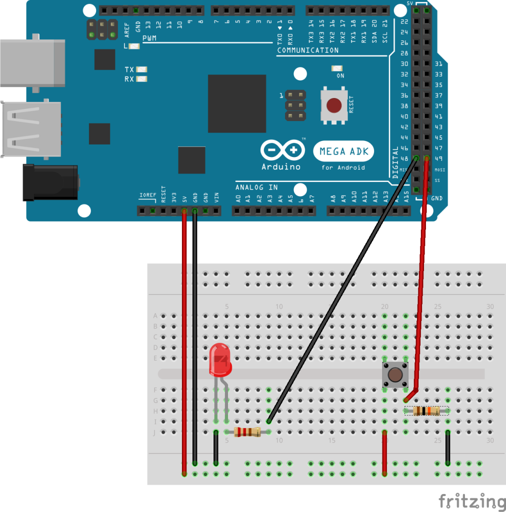
For out test we have to connect the status LED and the push button to the Arduino Mega. The LED is connected to pin 48 of the Arduino Meag using a 220 Ohm resistor. Pin D49 is hold on GND by a 10 kOhm resistor and is pulled to +5V by the switch. So the setup for LED/push button for the Arduino Mega looks like on the following sketch:

Finally, we have to connect a power supply and a load to the HSS shield. The supply voltage can be higher than the +5V supply of the Arduino. I chose a 12V power supply (which is running at about 15V without load) and a light bulb as load. Both is connected to the HSS shield using alligator clips. It’s not a setup for safe operation but for a few first tests under surveillance it was working.
Switching a load
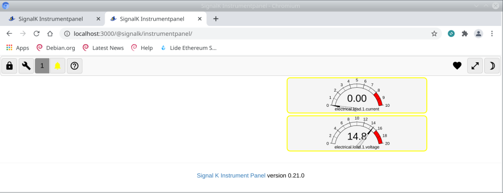
After the hardware setup for the Arduino is completed and the sketch is compiled and uploaded we can start the first tests with the HSS shield. The switching is still done completely local on the Arduino but supply voltage and current are read and sent to the SignalK server. You have to start the SignalK-Server like configured in one of the last posts on the Raspberry PI (or your PC) and then start (or reset) the sketch on the Arduino. If the IP/Port etc. in the Sketch is configured right you now should see the messages of the Arduino in the Dashboard of the SignalK server. Now open “Webapps->@SignalK/Instrumentpanel” and configure two displays as shown in “Arduino Uno as SignalK Source” for the paths “electrical.load.1.current” and “electrical.load.1.voltage”. Without load you should then have an output similar to the following, depending on the kind of display you configured:
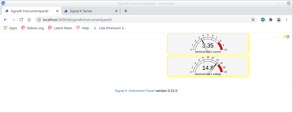
After switching the load on, in my setup i have the following picture:
Status and next steps
Now, we have the HSS shield running together with the Ethernet shield, we can communicate with the SignalK server and we can switch a load and read their status. Besides a simple display we can also use the current to implement further things e.g. a SW fuse. Also, there is much more status information available like e.g. open or shortened load. But before we dig deeper in that direction, we want to close the chain for switching “through” the SignalK server and read the switch state for the load from there.
References
Unfortunately, some of the references are in german but i’ll try to extend it with english references in the future.
[1] P. Horowitz, W. Hill, Die Hohe Schule Der Elektronik Teil 1: Analogtechnik, deutsche Ausgabe, Aachen: Elektro-Verlag, 1996. S. 137 und S. 149
[2] Infineon, PROFETTM +2 12V Grade 1 Product Brief, München, Infineon, 2021, Document number: B127-I0419-V6-7600-EU-EC-P
[3] Infineon, PROFETTM +2 12V Ardunio Shield User Manual Rev 1.0, 2019, S. 6 und S.10