From the beginning on we had the challenge that our Jeep WJ (4.7 V8) had a tendency to become hot, especially when going uphills. We never really tried if it would overheat but early reduced the load (the head gaskets thanked us). All the time we have been wondering if we have a defect in the cooling system or if it is generally a bit weak. Indeed over the time, some issues with the cooling system have been fixed. I’ll give a short overview before going to the PWM-relay / electric fan in more detail. One reason that it took a while to get everything fixed is also that the cooling system has quite some reserves, so if there is an issue you only notice when you have challenging conditions.
Part 1: Coolant
We had a little curiosity at the very beginning with the new Jeep: When we stopped the Jeep, the coolant sometimes started to boil (over). The solution was simple: Changing the coolant. Even if it was still looking good, probably it’s been so old that some ingredient was reducing the boiling temperature.
Part 2: Becoming hot during hill climbing
On our first tour across the Alps to Sardinia we experienced the next problem: The temperature started rising during long hill climbing. After that tour, I changed the viscous fan. The defective one was running for a short moment each engine start but seemed to never engage during driving. Also, I noticed that a wire of the electric fan was disconnected. After reconnecting, the electric fan ran sometimes until one day it was running through also after engine stop and then it never started again. As the engine temperature seemed to be fine always, I didn’t care a lot. The next Sardinia tour then brought us closer to problem 3:
Part 3: PWM-Relay and Electric Fan
During the next Sardinia tour thermally the engine ran much better. The only bit strange thing was that after arriving at a mountaintop, the temperature was a bit over normal, but still only the viscous and not the electric fan was running. After buying a (heavy) caravan, also during normal hill climbing the engine temperature started rising again. As the electric fan still seemed to be dead, this was a good reason to have a closer look. What’s the problem now? The strange behavior when running last time could indicate a problem with the relay. But also the electric motor, the wiring or even the engine ECU could have a problem. So better check everything until the defective part is identified.
When checking the workshop manual while searching for the Relay (which actually is pretty well hidden) I first time read the term PWM-Relay. Before checking the part, we have to understand: What the heck is a PWM-Relay?
- A relay is a electrically operated switch, which using a (typically small) control current is switching a heavy load. They are also used in vehicles to switch loads, one of them might be the cooling fan
- PWM is the abbreviation for “Pulse Width Modulation”, typically an electrical signal is toggled between the binary states “on” and “off”. The duty cycle, which is the proportion of “on”, can vary from 0% to 100%. Besides the application to convert digital to analog signals, it’s useful for power electronics because the power semiconductors are only in the states “off” or “saturated” where they have low losses. Besides other applications, PWM can be used to control electric motors.
Now, it might theoretically be possible to operate an electro-mechanical relay in a “PWM” kind of operation. Because of the high switching frequency which is required to control an electric motor, chances are that the mentioned “PWM-Relay” actually is a power semiconductor, probably a field effect transistor (FET).
A FET has three terminals, e.g. a n-channel-FET (there are many different types) can be used as a switch: the “drain”-terminal is connected to the load, “source” is connected to ground and using “gate” the load can be switched on or off. If gate is positive, the load is switched on. The advantage is that because of the high resistance of the gate-terminal, only a small current is needed to control the load [1]. Alternatively, the FET can be between voltage source and load (“Drain” at the voltage source, the load at “Source”).
To test a FET, we have to connect “Drain” to a voltage source, apply a control voltage to “Gate” and check if the FET is switching correctly. If the FET is working correct, “Source” has to be just below the voltage at “Gate”. If “Gate” is open, no voltage must show at “Source”. As voltage source I used a charger with power supply functionalty. But, before testing the relay we first have to find it and to figure out the PIN layout.
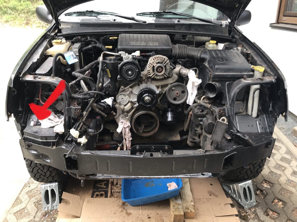
In my Jeep WJ, the PWM relay is mounted onto the vehicle body on the right side (passenger side) below the headlights. I checked (and replaces) the relay when I had the full front mask removed. Probably, anyway the relay is not accessibly without removing the front mask. Other models might have an opening to access the relay. In picture 1 below the position of the relay is marked by a red arrow.
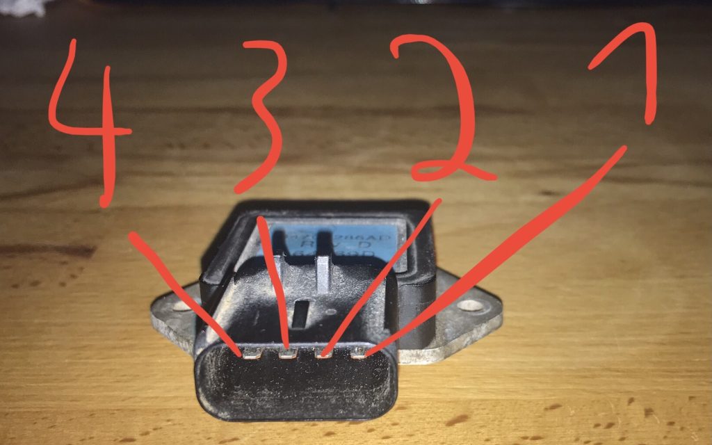
Unfortunatly, I wasn’t able to find a pin layout for the PWM relay in the workshop manuals I have. But I was able to find some hints to derive the pin layout on this web page: https://troubleshootmyvehicle.com/jeep/4000/how-to-test-the-pwm-relay (I have a 4.7 V8, but the pin layout seems to be the same for the 4.0 I6). The pin layout is shown in table 1 and the pin numbers in picture 2. A word of caution: I can not guarantee that the pin layout always is the same – better check and plausibilize yourself.
| Pin | Functionality |
| 1 | +12V / “Drain” |
| 2 | Control Signal / “Gate” |
| 3 | Electric Fan Output / “Source” |
| 4 | Ground |
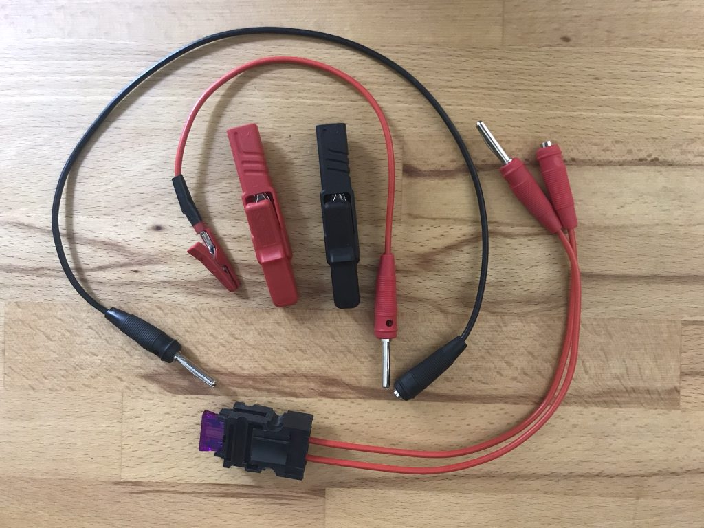
After functionality and pin layout have been clarified, the wiring of the PWM relay, the electric fan and the relay itself can be tested. The test of wiring and fan must be done at the vehicle. To be able to access the pin’s at the wiring for the tests, I soldered the “test wires” shown in picture 3. The narrow (isolated!) clamps are small enough to get into the plugs. Using the banana plugs, the cables and crocodile clamps can flexibly be wired together. Additonally, I have a wire with a fuse which I can use to be safer in case there is a shortcut somewhere. Attention: The clamps and cables survived some short tests but are not designed for high continous currents!
Test of the Wiring
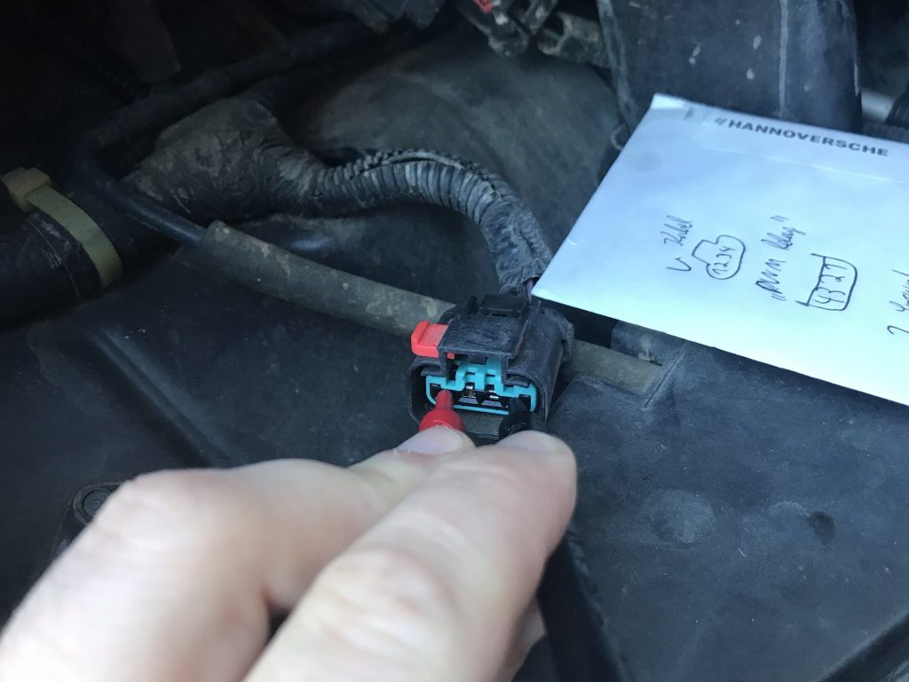
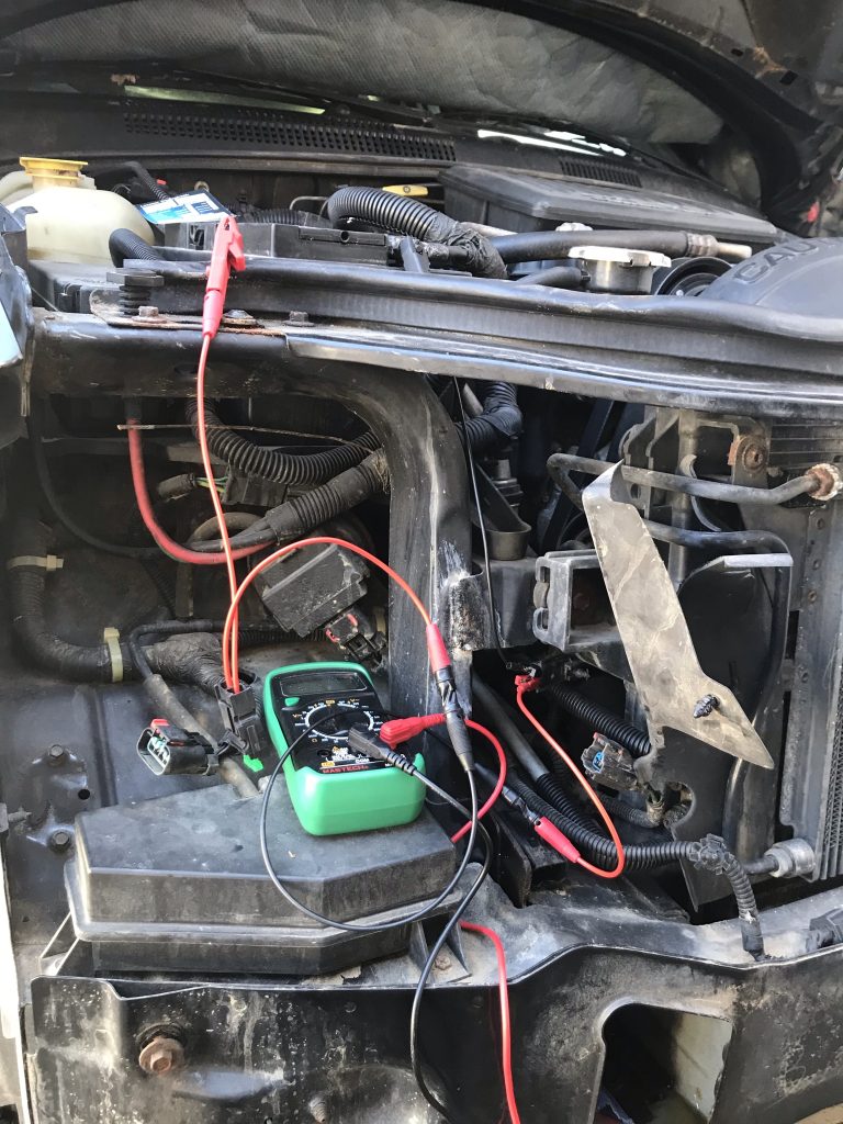
Using the known pin layout, some first tests of the wiring can easily be done using a multi meter (picture 4): Between Pin 1 (+12V) and ground there should be “12V”. Between positive battery terminal and Pin 4 (ground) there should also be “12V” and between Pin 4 (ground) and ground there should be 0V. If it’s sure the Pin 4 is the ground pin, you can also check there is no additional resistance between Pin 4 and body – but maybe better disconnect the battery first.
Test of the electric fan
Using the test cables shown above, I was also able to test the electric fan. Therefore, on of the cables shown in picture 3 is connected to the ground of the electric fan and to ground of the vehicle, in this case using negative terminal of the battery. The fuse is looped into the plus wire between battery and electric fan, see picture 5/6/7. After connecting the positive clamp to the positive battery terminal, the electric fan should run. Don’t run it to long – clamps and wires are not designed for continous high currents.


Testing the PWM relay
To test the PWM relay, a power supply is required. I used a charger which also has a power supply functionality and the test wires shown in picture 3. Pin 1 is connected to +12V and Pin 4 to ground of the power supply. No voltage must show up at Pin 3 of the PWM-Relay, which can be tested using the multi meter. If Pin 2 is also connected to +12V, also on Pin the +12V have to show. This wasn’t the case using the defective PWM relay. After replacing the relay, the fan was running again as expected (e.g., it shall run when A/C is turned on).
How did the story continue…
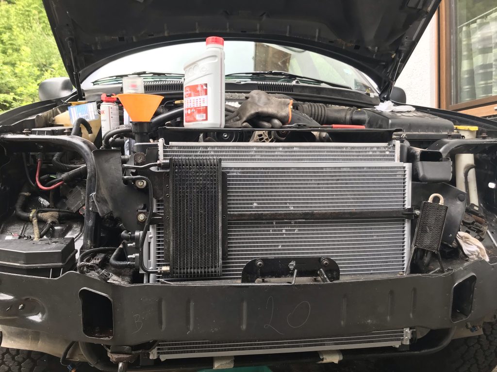
Shortly after the new PWM relay, the Jeep also got a new radiator. Not because the radiator was defective, but the condenser of the air condition was and had to be replaced. As the radiator anyway was accessible now and sometimes the automatic transmission cooler inside fails first, which leads to automatic transmission fluid and coolant mixing – not something you want to have – I also replaces the radiator, as you can see on picture 8 below. As you can see in picture 1, that is a good opportunity to alse replace water pump, thermostat including housing, belt tensioner and oil pressure switch. The automatic transmission auxilliary cooler was not replaced because I didn’t get a spare part – today, it is replaced but that’s another story…
Since changing the PWM relay (and all the other parts), also with heavy trailer and in hot temperature there was never a problem with heavy coolant temperature rises again. But I have to admit until now there haven’t been extreme tests like a crossing of the alps.
[1] P. Horowitz, W. Hill: Die Hohe Schule der Elektronik Teil 1: Analogtechnik, Translation of second edition of “The Art Of Electronics”, Aachen, Deutschland: Elektor-Verlag, 1996, S. 137 und S. 140