After we set up a the Raspberry PI with a SignalK server in the last step, this time we will introduce a sketch for an Arduino UNO (also works with an Arduino Mega) which reads in sensors and sends their values to the SignalK server using SignalK JSON over UDP. As inputs we chose an HC-SR04 ultrasonic sensor which can be used e.g. as a tank level sensor and a Bosch BMP280 temperature/pressure sensor connected by I2C and an analog value. We’ll show the values on the @SignalK/Instrumentpanel webapp already existing on the Raspberry PI.
The Arduino Uno (and also the Arduino MEGA) have very little memory (SRAM and Flash) and a slow processor. In this first step we want to figure out if it’s still enough to send few lower frequency SignalK signals. On success we will add further features. On failure, e.g. if the performance is to low, we’ll have to look for an alternative solution.
Before we start, we need to have a little deeper look at the SignalK specification. First there is a a full and a delta model defined. The full model contains a lot of entries and probably is a bit oversized for the Arduino Uno. But there also is a Delta model which contains an update to an existing full SignalK model. Therefore, for an Arduino updating a few sensors, the delta model seems to be more appropriate. The full model can then be build up on a more powerfull server.
Considering the communcation of the SignalK message, again there are several option. One is using a HTTP REST API which because of the HTTP implementation required on the node again looks a bit to big for the Arduino Uno. As alternative, Signal K may also be sent over TCP or UDP. As UDP is a pretty lightweight option, we’ll use this option here. It’s also possible to stream Signal K by a serial port, e.g. the USB to serial on the Arduino Uno, which we’ll also use because it might help for development and debugging.
Hardware and Software in use
- PC with Debian GNU Linux 10.0
- Raspberry PI 3 with Raspbian Buster Lite (02.12.2020) (Configuration is described here)
- Arduino 1.8.13
- Arduino UNO or Arduino MEGA
- Wiznet W5100 Ethernet-Shield
- HC-SR04 Ultrasonic Sensor
- For the Ultrasonic the NewPing-Library Release 1.9.1
- A Bosch BMP280 I2C-Sensor
- The BMx280MI-Library Release 1.2.0
- The Arduino-AVR Sketch on our Github
Details of the sketch
Before you can have a look at or compile the sketch you have to download it from github. Either you download it as an archive from here: https://github.com/Vehicle-Hacks/Arduino-SignalK/releases/tag/v0.1.0. Or you clone it using the “git” command:
git clone -b v0.2.0 https://github.com/Vehicle-Hacks/Arduino-SignalK.gitWithout “-b v0.1.0” you’ll get the current master, which might differ in details from the version used here. The sketch used here you’ll find in the file: Arduino-SignalK/Arduino-AVR-SignalK/Arduino-AVR-SignalK.ino.
What we roughly have to do is to cyclically read in the sensor data, convert it to JSON strings and send it out to a Signal K server. Typically, in a distributed environment you’ll also want to add a common time stamp. Therefore, we need to get the synchronized time for which a well established protocol is the Network Time Protocol (NTP) which we’ll also use here.
In the sketch we’re using some #define’s to activate or deactivate functionalities. This is done at the beginning of the sketch. By default, all the options are active. If you don’t have a specific sensor, you can dactivate the according functionality by commenting out the #define:
#define SERIAL_OUTPUT   // Send SignalK messages on serial output.
#define USE_BMX280      // Read in temperature und pressure from BMx280.
#define USE_TANKLEVEL   // Measure tank level using an HC-SR04 Ultrasonic.
The first line of the next section contains the MAC address of the ethernet shield. On my shield there is a sticker on the bottom side of the shield. You have to remove the shield to find it. The following two lines contain the IP address of the SignalK server (the Raspberry PI we set up in the last step) and the UPD port to which the Arduino will send the data:
byte mac[] = {0x90, 0xA2, 0xDA, 0x11, 0x05, 0xAA};
IPAddress signalkServer(192, 168, 178, 31); //SignalK Server Address
.
.
.
const unsigned int signalkPort = 8375;      // SignalK Port of the SignalK Server for UDP communication
Then there is line which contains the name of the time server we’re using. I have a Fritz!Box as router which can act as a time server. Probably, other routers can also serve this purpose. So first, best is to try your router. If your router doesn’t work, you can also try to use a public time server like time.nist.gov. This might create a large delay which you then have to consider in the loop function:
const char timeServer[] = "fritz.box";In the next section, we configure the HC-SR04. The first two lines contain the pins for trigger end echo reception. The next line contains the maximum distance the HC-SR04 will evaluate. The following two lines configure the tank in use: “tankFull” is the distance between sensor and fluid level when the tank is completely fille, “tankEmpty” the distance when the tank is completely empty.
const int echoSendPin = 2;
const int echoReceivePin = 3;
const int maxDistance = 320;
float tankFull  = 0.05;
float tankEmpty = 0.75;
For the BMx280 there is not much parameters to choose. The last parameter is the pin which is used for the analog input:
const int analogPin = A0;After the includes and the configuration of the parameters there is a section which contains a lot of string definitions:
const char string_0[] PROGMEM = "{"
                           "\"updates\": [{"
                           "\"source\": {"
                           "\"label\": \"Arduino SignalK\","
                           "\"type\": \"signalk\""
                           "},"
                           "\"timestamp\": \"";
.
.
.
The reason to define the string in this way is that the JSON strings need a lot of memory, but the Arduino only has a little. Especially the 2kB SRAM of an Arduino are pretty limited. To save some memory, we put the strings into the much bigger flash where they’ll only be read when they are used for sending. That’s why we are using PROGMEM here. The code to read the strings out will be described in the loop() section. A short remark for the naming of the strings: This might help us later to automate things a bit.
After the string definitions there is the actual code. First there is the setup() function in which interfaces and libraries are initialized but there is nothing special.
In the loop() function the first thing is to send a NTP request to the server (we don’t have any details here as it would be to much. Maybe later in a separate post). As we have to wait a (milli-)second, we use the time to read the SignalK-header from the flash into the SRMA using strcpy_P(). After reading the string, we write the header into the UDP package and – if configured – onto the serial interface. Next we read the time stamp from the answer of the NTP server. If we use a public time server, we might have to add a delay before to give the answer enough time to arrive.
After writing the header with the timestamp, the next steps are – if configured – to read the tank level, the BMx280 and the analog input and to write them into the UPD package (and onto the serial interface). Similar to the header, we always read the JSON strings from the flash using strcpy_P(). At the end, the UDP package will be sent. This function is running in permanent loops. On the Arduino Uno we’ll reach a few Hz frequency.
Hardware Setup
Before we can start testing, we have to set up the hardware. Therefore, i used an Arduino Uno, an ethernet shield (Wiznet W5100) and a breadboard. You can see how everything is wired in the fritzing picture:
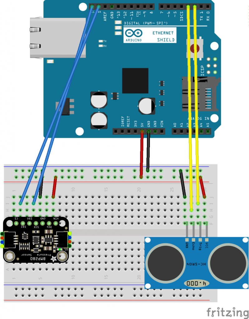
The ethernet shield is placed on top of the Arduino Uno. Here the required wiring is in a table:
| Arduino Pin | Component Pin |
| 5V | HC-SR04 VCC / BMP280 VCC |
| GND | HC-SR04 GND / BMP280 GND |
| D2 | HC-SR04 Trigger |
| D3 | HC-SR04 Echo |
| SDA | BMP280 SDA (SDI) |
| SCL | BMP280 SCL (SCK) |
Testing the sketch using serial output
From here on we’ll need the Raspbery PI with the SignalK server as set up in the first step. First we’ll test, if the SignalK server can receive valid data over the serial interface. This way, we can avoid running in problems with the network configuration. Therefore, we need to activate the serial interface:
#define SERIAL_OUTPUT   // Send SignalK messages on serial output.
#define USE_BMX280      // Read in temperature und pressure from BMx280.
#define USE_TANKLEVEL   // Measure tank level using an HC-SR04 Ultrasonic.
After checking the configuration, we can compile the sketch using the Arduino IDE and upload it to the server. We can start the SignalK server using the default configuration:
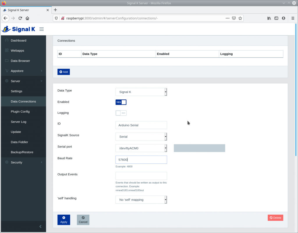
pi@raspberrypi:~/signalk-server-node $ ./bin/signalk-serverWe can open the GUI of the SignalK server by opening the port 3000 on the raspberry pi using a webbrowser. Therefore, type the URL: “http://raspberrypi:3000” into the address bar of the browser. After that, in “Server->Data Connections” we click onto the button “Add” to add a serial connection. As “Input Type” we use “SignalK”. We set “Enabled” on “yes” and “Logging” on “no”. The ID we can choose freely – e.g. “Arduino Serial”. The “SignalK Source” is “Serial”, the Arduino will usually use the device /dev/ttyACM0. The “Baud Rate” in the sketch is configured to 57600. For the last two field we can keep the default value. After these steps, the configuration of the serial interface should look like in the screenshot:
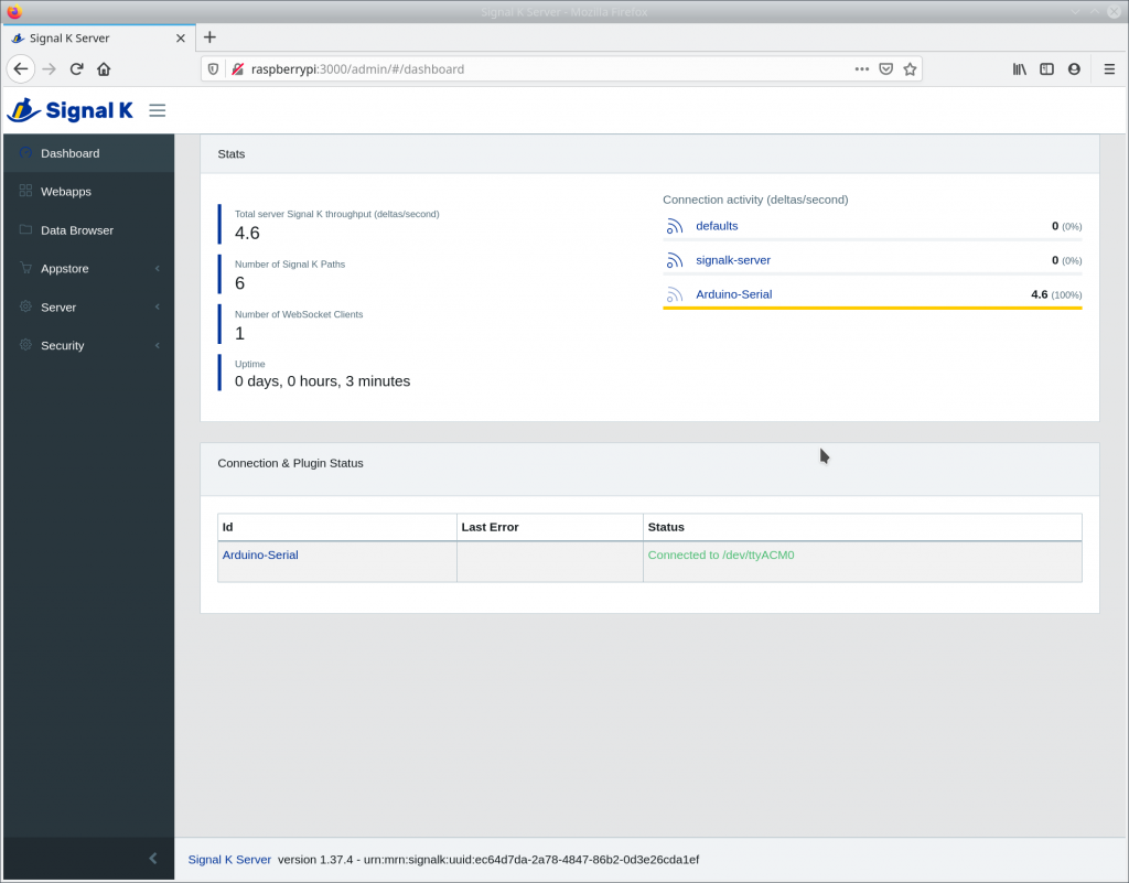
The settings will be saved by clicking “Apply”. It might be possible to restart the SignalK server for the interface to work. If it’s working, it will be shown in the “Dashboard” and the data rate should be above 0. In my case, it’s showing 4.6 packages/s:
Configuring the instrument panel for the Arduino
If we now open “@SignalK/Instrumentpanel” from the “Webapps”, you can visualize the data sent by the Arduino. After opening, the panel is empty. If you click on the wrench top left, you open the configuration dialog. There you have to activate “Show on grid” for all signals. In “Edit” you can additionally switch from digital to analog view.
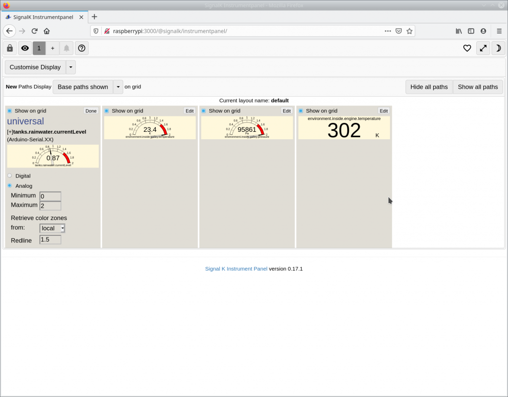
If you click on the eye-symbol top left to switch back to the view mode, you should see the selected signals:
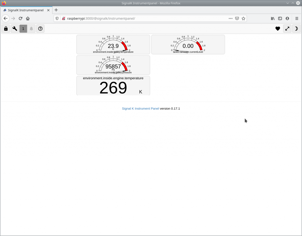
Now the first signals are sent from the sensors to the web browser by the SignalK server. Play around with the sensors and watch the values changing!
Using the sketch with UDP output
To use the Arduino as UDP sender the IP Address and the port of the SignalK server have to be configured in the sketch. If you don’t know the IP address of the Raspberry Pi, you can use the “ip addr” command to show the configuration of all the network interfaces. The ethernet device usually is called “eth0”. The serial output can now be deactivated to reduce the load a bit:
//#define SERIAL_OUTPUT   // Send SignalK messages on serial output.
.
.
.
IPAddress signalkServer(192, 168, 178, 31); //SignalK Server Address
.
.
.
const unsigned int signalkPort = 8375;      // SignalK Port of the SignalK Server for UDP communication
After configuring, compile the sketch using the Arduino IDE and upload it to the Arduino. First, using the tool netcat we check if the Arduino is sending valid data to the Raspberry PI. Therefore, we start netcat listening for an incoming connection on the defined IP address and UDP port on the Raspberry PI:
nc -l -u 192.168.178.31 8375If the sketch is loaded on the Arduino and running without errors, you should receive an output similar to the following:
pi@raspberrypi:~/signalk-server-node $ nc -l -u 192.168.178.31 8375
{"updates": [{"source": {"label": "Arduino SignalK","type": "signalk"},"timestamp": "2021-01-24T16:8:23","values": [{"path": "tanks.rainwater.currentLevel","value":0.87},{"path": "environment.inside.galley.temperature","value":23.34, "units": "K"},{"path": "environment.inside.galley.pressure","value":95871.00, "units": "Pa"},{"path": "environment.inside.engine.temperature","value":269.30}] }] }{"updates": [{"source": {"label": "Arduino SignalK","type": "signalk"},"timestamp": "2021-01-24T16:8:23","values": [{"path": "tanks.rainwater.currentLevel","value":0.87},{"path": "environment.inside.galley.temperature","value":23.34, "units": "K"},{"path": "environment.inside.galley.pressure","value":95871.00, "units": "Pa"},{"path": "environment.inside.engine.temperature","value":269.30}] }] }{"updates": [{"source": {"label": "Arduino SignalK","type": "signalk"},"timestamp": "2021-01-24T16:8:23","values": [{"path": "tanks.rainwater.currentLevel","value":0.87},{"path": "environment.inside.galley.temperature","value":23.34, "units": "K"},{"path": "environment.inside.galley.pressure","value":95869.00, "units": "Pa"},{"path": "environment.inside.engine.temperature","value":268.95}] }] }{"updates": [{"source": {"label": "Arduino SignalK","type": "signalk"},"timestamp": "2021-01-24T16:8:23","values": [{"path": "tanks.rainwater.currentLevel","value":0.87},{"path": "environment.inside.galley.temperature","value":23.34, "units": "K"},{"path": "environment.inside.galley.pressure","value":95868.00, "units": "Pa"},{"path": "environment.inside.engine.temperature","value":269.30}] }] }
.
.
.
Now you can start the SignalK server using the default configuration:
pi@raspberrypi:~/signalk-server-node $ ./bin/signalk-serverNow again open the GUI using a webbrowser and the address “http://raspberrypi:3000”. Now you have to configure the UDP connection for the SignalK server. As “Input Type” you again choose “SignalK”, “Enables” is “Yes” and “Logging” is “No”. The ID can be choosen freely – e.g. “Arduino UDP”. As “Source” we choose “UDP”, as Port 8375 (the same as in the Arduino sketch). Finally, the configuration of the UDP connection should look like in the screenshot:
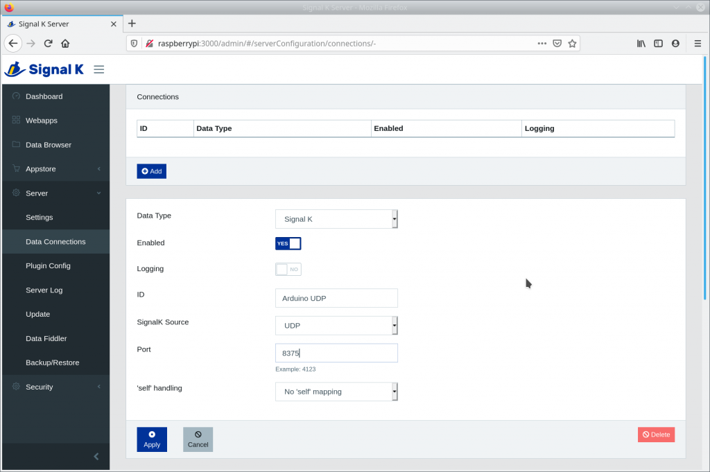
The connection will be added after you clicked on “Apply”. It might be necessary to restart the server for the connection to work. As described in the preceding section, you can open “@SignalK/Instrumentpanel” from the “Webapps” and configure it to show the signals send by the Arduino.
Results and next steps
So now we have a first sketch for the Arduino reading in sensor and sending their data to the SignalK server. The update rate is a few Hz and not that high, but should be enough for some applications. And probably there is further potential for optimization. What we can also optimize is the accuracy of the time stamps and currently, a connection error can only be fixed by a hard reset of the Arduino. But the achieved results suggest continuing on the chosen path. We’ll keep you up to date and will continuously work on this site!